Array
(
[id] => 4128
[site_id] => 1
[project_id] => 478
[cate_id] => 794
[thumb] => Array
(
[id] => 3757
[cate_id] => 1
[folder] => res/202408/26/
[name] => c4141cd88ce3d0cb.jpg
[ext] => jpg
[filename] => res/202408/26/c4141cd88ce3d0cb.jpg
[ico] => res/_cache/_ico/37/3757.jpg
[addtime] => 1724679082
[title] => 3KG ozone generator system configuration
[attr] => Array
(
[width] => 500
[height] => 400
)
[note] =>
[session_id] =>
[user_id] => 0
[download] => 0
[admin_id] => 1
[mime_type] => image/jpeg
[gd] => Array
(
[auto] => res/_cache/auto/37/3757.jpg
[thumb] => res/_cache/thumb/37/3757.jpg
)
)
[content] => 1.1 Overview
1.1.1 This plan is a wastewater treatment project, 1 set of air source 3kg/h ozone generator system.
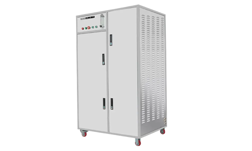
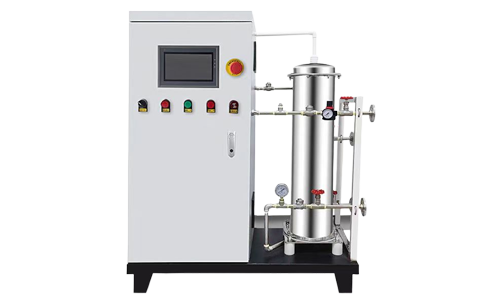
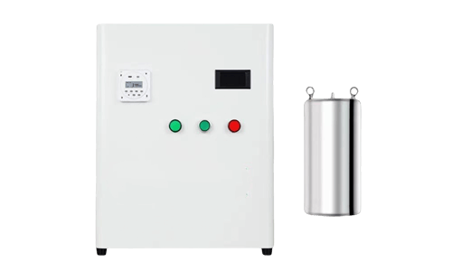
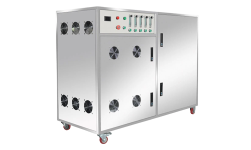
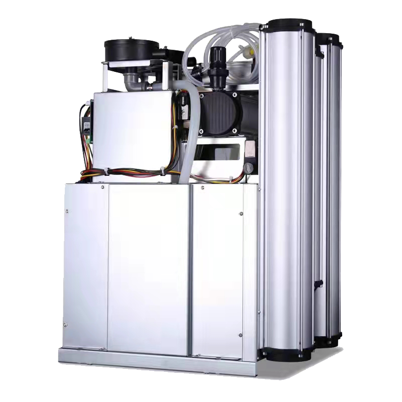
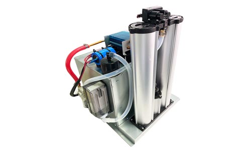
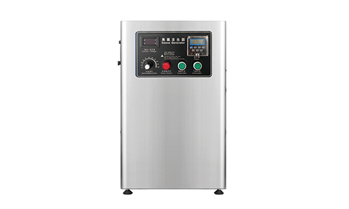
1.1.2 This project consists of ozone generator, air source treatment system, closed-loop cooling water system, control system, tail gas treatment system, etc. The ozone generator system includes 1 set of air source 3kg/h ozone generator and its matching automatic control and instrument valves. KQ Environmental Protection Technology, as a professional ozone equipment R&D, production and manufacturing supplier, provides stable and reliable ozone preparation systems and peripheral supporting products, and provides technical and process support.
1.1.3 This plan stipulates the technical requirements for the design, manufacture, supply, installation and commissioning of ozone generation equipment.
1.1.4 The supplier guarantees that the products provided comply with this plan and related requirements, and meet the corresponding national and industry standards.
1.1.5 Matters not covered in the plan shall be resolved by mutual consultation between the two parties and confirmed in writing.

1.2 Design conditions
1.2.1 External circulation cooling water conditions
Pressure: Overcoming the pressure loss of the plate exchanger (about 0.05MPa); Temperature: ≤28℃; Turbidity: ≤1 degree (NTU); COD: ≤50mg/L; Suspended matter: ≤10mg/L; Chloride content: ≤250mg/L; Solid particles: None.
1.2.2 Internal circulation cooling water quality conditions
Pure water or demineralized water.
1.2.3 Power supply conditions
Power supply conditions for ozone generation equipment, 380V/3ph/50Hz, three-phase five-wire system.
1.3 Design plan
Operating parameters and requirements provided by the buyer: [**]ccording to the specifications required by the owner.
[**]ccording to the project design requirements, the supplier provides a complete ozone generator system, including 1 set of air source 3kg/h ozone generator, a single set of ozone output of 3kg/h, concentration 15-25mg/L. The ozone generator system consists of an ozone generator, a control system, an internal circulation cooling water system, an air source treatment system, and an exhaust gas recovery system.
Operation cost: 31KW/h for the air source system, 21KW/h for ozone, 4KW/h for the cooling system, a total of 56KW/h.
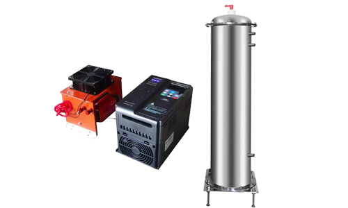
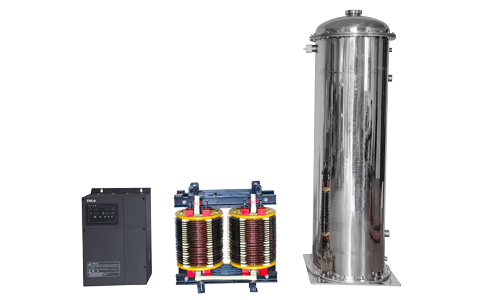
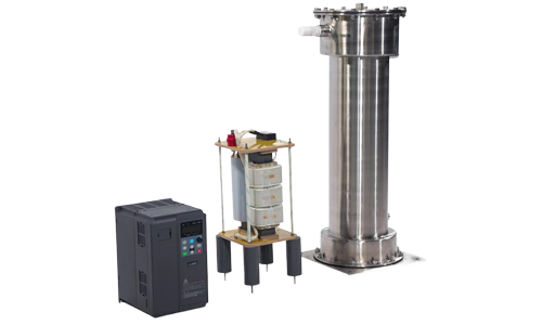
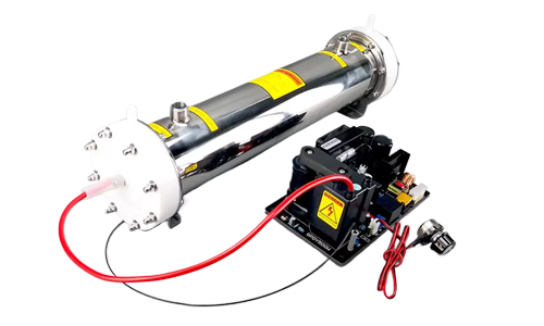
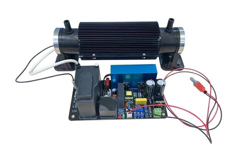
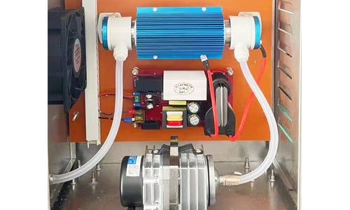
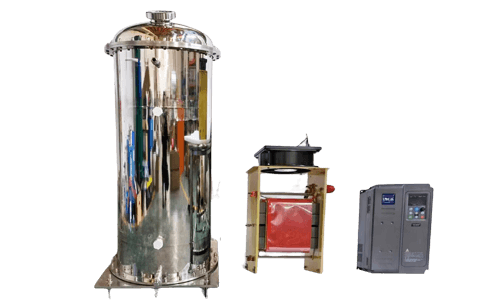
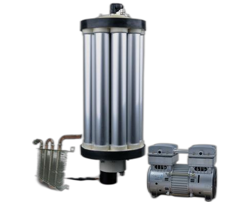
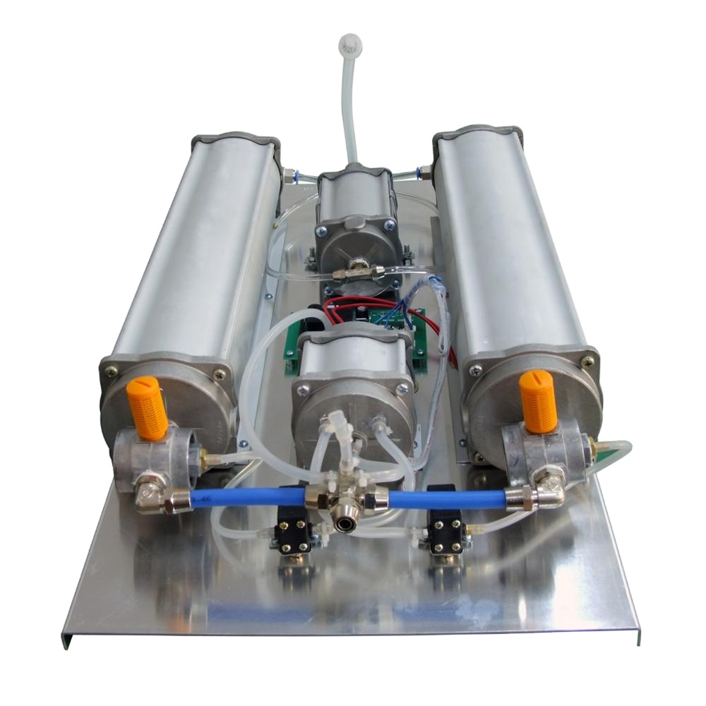
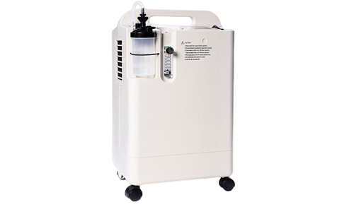
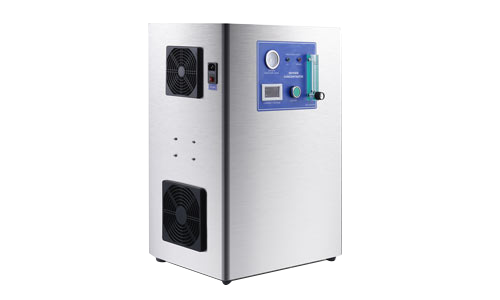
The ozone generator consists of two parts: an ozone discharge chamber and an ozone power supply device; the air source treatment system includes an air compressor, a refrigerated dryer, an adsorption dryer, an air filter, etc., or a liquid oxygen system.
1. Main technical parameters of ozone system
Main equipment utility consumption parameters
Power supply requirements:
380V, 50Hz, 3ph, three-phase five-wire system
System power consumption: 56KWh
Distribution capacity: 150KV[**]
Circulating cooling water: 3-6 m3/h
Cooling water filling volume: 2.0 tons (provided by the buyer)
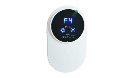
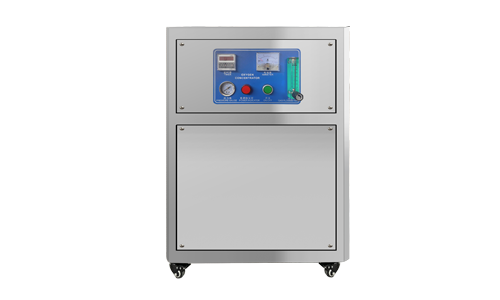
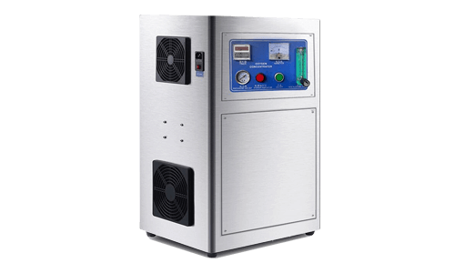
Ozone master control cabinet
Name: Fully automatic PLC panel control system
[**]dopting Siemens display integration

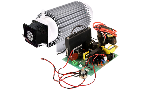
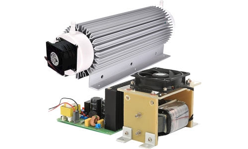
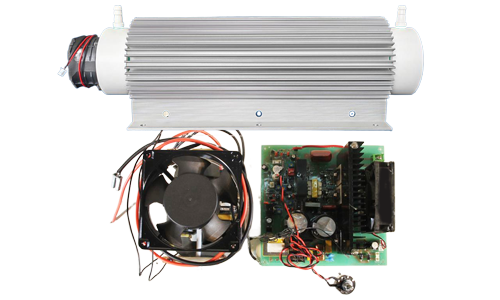
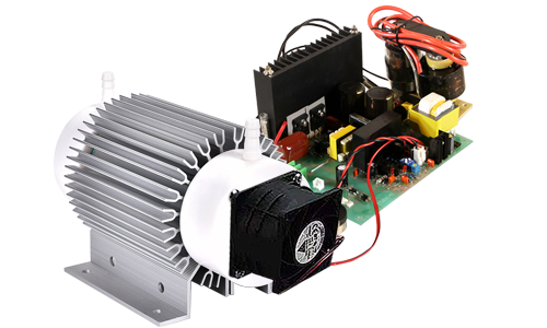
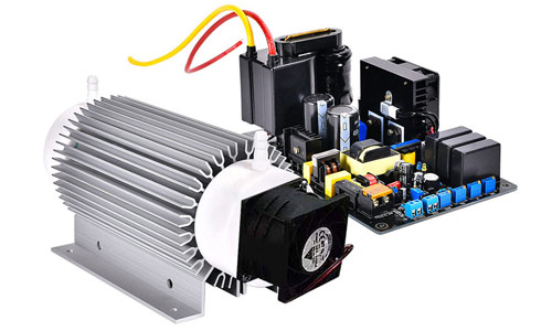
Ozone generator
Name: 3kg/h honeycomb ozone generator
Model: 3KG/H, N=21KW
Rated ozone output: 3kg/h
Input power: 380V/50Hz/3ph
Rated power: 21KW
Output adjustment range: linear adjustment
Unit ozone power consumption: 9KWh/kgO3 @ cooling water 25℃
Ozone concentration: 80-120mg/L @Cooling water 25℃
Ozone quantity adjustment: 10-100%
Working pressure: 0.095±0.05Mpa
Ozone outlet pressure: 0.1MPa (G)
Gas volume required: 36Nm3/h
Cooling water volume: 6-8m3/h
Gas pipe interface: DN32
Water pipe interface: DN40
Gas source conditions
Raw materials: air source
Oxygen content: 21% (VOL)
Gas flow rate: 3.6Nm3/min
Dew point: ≤-60℃@1 standard atmosphere
Gas supply pressure: 2~5bar-g
Gas supply temperature: ambient temperature 25℃
Particle size in gas: ≤0.01μm (no metal components)
Oil content: ≤0.01mg/m3
Cooling water conditions
Cooling water volume: 3-6m3/h
Cooling water pressure: 2bar
Cooling water temperature: inlet range 5-30℃ Outlet temperature rise 3-5℃
Cooling water quality: PH value 6.5-8 Chlorine content ≤100mg/L Suspended solids ≤10mg/L
Cooling water quality: COD ≤50mg/L Turbidity ≤1NTU
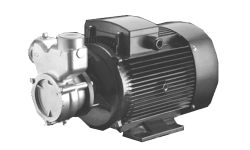
[**]ir compressor
Model:
Q=3.6Nm3/min, N=30KW
Power: 30KW
[**]ir flow: 3.6Nm3/min@7bar
Working pressure: 8.0bar
Dimensions: 1200*820*1135mm
Outlet size: G1.5"
Noise: 76±3dB([**])
Weight: 491kg
Power supply: 380V/50Hz/3ph
[**]ir tank
Model:
V=0.6m3, P=0.8Mpa
Capacity Volume: 0.6m3
Working pressure: 8.0bar
Dimensions: Ф650*1500mm
Material: Carbon steel
Interface size: DN80
Weight: 130kg
Refrigerated dryer
Power: 0.9KW
[**]ir handling capacity: 3.8Nm3/min@7bar
Dimensions: 930*500*910mm
Weight: 77kg
Interface size: G2
Power supply: 220V/50Hz/1ph
[**]dsorption dryer
Cooling method: Heatless regeneration
Power: 0.05KW
[**]ir handling capacity: 3.8Nm3/min@7bar
I. Ozone system composition and system flow
5.1 Ozone system composition
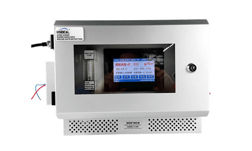
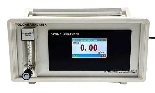
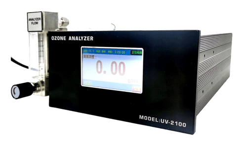
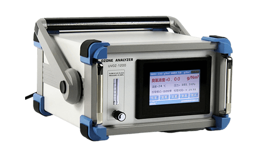
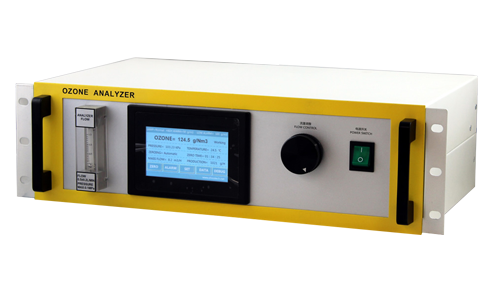
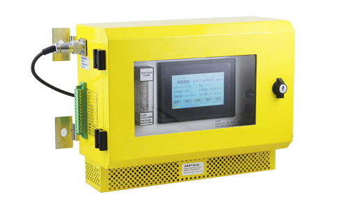
The ozone system is mainly composed of ozone generator, gas source system and control system. The ozone generator consists of two parts: an ozone generator (ozone discharge chamber) and an ozone power supply device; the gas source system includes an air compressor, a refrigerated dryer, an adsorption dryer or an oxygen generator, an air filter, etc.; peripheral equipment such as an ozone concentration detection device can be equipped according to the needs of the buyer.
5.2 System Flow
The schematic diagram of the air source/oxygen-rich source ozone generator system is as follows:

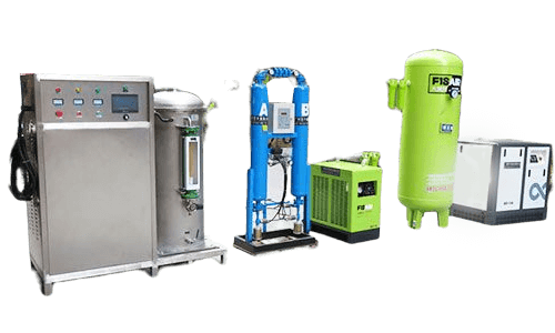
The air treatment system consists of an air compressor, a refrigerated dryer, an adsorption dryer or an oxygen generator, an oil-water separator, and an air filter to provide a qualified gas source for the ozone generator. The air compressor uses a screw air compressor with high gas outlet efficiency, low noise, and low operating costs. The air storage tank is used to pre-store and buffer the compressed air provided by the air compressor, and to keep the compressed air pressure and air flow constant to ensure the use conditions of the downstream purification equipment. The refrigerated dryer cools and condenses the compressed air under saturation to remove water. Under normal working conditions, it can remove about 80% of the water in the compressed air. It has a large water removal capacity and low energy consumption. It belongs to shallow water removal and must be dried and coordinated to meet the requirements of ozone discharge. The adsorption dryer is a dehumidification and purification device that uses the pressure swing adsorption principle and the heatless regeneration method to dry the compressed air. It belongs to deep water removal, and the air source can reach the atmospheric dew point of about -50℃. The filter includes main pipeline filtration, oil removal filtration, dust removal filtration, etc., to ensure that the oil content of the air source entering the adsorption dryer is less than 0.01mg/m3, and the dust particle size of the air source entering the ozone generator is less than 1μm or even 0.01μm.

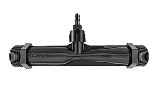
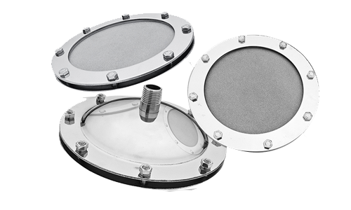
The qualified raw gas source is reduced by the pressure reducing valve, and the dew point meter monitors the inlet dew point online, and then passes through the valve, pressure gauge, and temperature display field to display the inlet pressure and temperature before entering the ozone discharge chamber. In the medium-frequency high-voltage electric field in the ozone discharge chamber, part of the oxygen is converted into ozone, and the product gas is ozonated gas. [**]fter pressure, temperature and flow monitoring, it enters the contact tank or oxidation tower. The contact tank (or oxidation tower) is equipped with microporous aeration disks, and ozone gas is added to the water body through the microporous aeration disks.
The control system uses PLC to connect with industrial control-level computers. The ozone generator adopts internationally advanced medium-frequency discharge technology, with CPU core control inside, and is designed with soft start and soft unloading functions. It can also smoothly and linearly adjust the ozone generator's added power to achieve 10%-100% adjustment of ozone production, minimizing the demander's operating costs.
[**]n ozone leak alarm is installed in the ozone preparation room. When the ozone leak in the preparation room exceeds the standard, the system decides to output an alarm, start the exhaust fan or shut down according to the detection signal.
The tail gas destroyer uses heating catalysis to decompose ozone, and the entire tail gas destroyer is controlled by the tail gas destruction box. The ozone concentration of the decomposed gas is less than 0.16mg/m3 and can be directly discharged into the atmosphere.
2. Utility conditions of the ozone system
6.1 Gas source conditions
[**]t the air inlet of the ozone generator, the gas source meets the following requirements:
1 Raw air
2 Gas demand m3/h (subject to technical parameters)
3 Dew point (under 1 standard atmospheric pressure) ≤-50℃
4 Gas supply pressure 2~5bar-g, fluctuation ±5%
5 Gas supply temperature ambient temperature
6 Particle size in the air ≤0.1μm, no metal components
7 Oil content <1ppm
6.2 Power supply conditions
The ozone generator uses a 380V/3ph/50Hz three-phase five-wire power supply, with an allowable voltage fluctuation range of ±5%. If it does not meet the requirements, a voltage stabilizer needs to be added. Try to avoid sharing a power supply with high-power and frequently started electrical equipment.
6.3 Grounding conditions
Since the ozone generator is a high-voltage discharge device, according to the provisions of GB 50169-2006 "Construction and [**]cceptance Specifications for Grounding Devices of Electrical Installation Engineering" and GB 14050-2008 "Forms and Safety Technical Requirements for System Grounding", the metal base and shell of the ozone generator should be safely and reliably grounded to ensure the safety of equipment and personnel.
Therefore, the buyer should pre-embed the grounding device in the ozone preparation room and lead the grounding flat iron to the ozone generator terminal.

6.4 Communication conditions
If remote communication is required, the two parties must first agree on the communication protocol. The supplier reserves the interface required for the communication between the PLC system and the buyer's control system, and the buyer provides cables and communication connectors.
6.5 Cooling water conditions
The heat generated by the ozone generator needs to be released, and the cooling system of the ozone generator is achieved by cooling water flowing through the outer wall of the discharge tube. [**]ny stainless steel is very sensitive to chloride ion corrosion, especially when the chloride ion concentration is high, it needs to be taken seriously: the ability to corrode is affected by water temperature and pH value. The higher the water temperature and the lower the pH, the faster the corrosion.
The buyer shall provide qualified cooling water source to the water exchange port of the board, which shall meet the following requirements: turbidity ≤ 1 degree (NTU), pressure ≥ 0.2Mpa, temperature ≤ 28℃;
6.6 Environmental requirements for the ozone room and precautions before installation
(1) The ozone generator and its supporting equipment are complete equipment when leaving the factory. No person or unit may dismantle equipment accessories, instrument valves, pipelines and other accessories at will without the permission of our company. The integrity of the equipment must be maintained. When the supplier's commissioning personnel find that the installation and construction party has the above phenomenon, they shall require the installation and construction party to restore the equipment unconditionally, otherwise the equipment commissioning will not be carried out.
(2) The equipment room should be away from dust sources, corrosive material sources; away from high temperature and humid environment; away from vibration sources; the room should be well ventilated and well lit. The room height should meet the needs of equipment installation and maintenance. The room temperature is about 5-30℃, and the humidity is <85%. [**]voiding excessive temperature in the machine room is a reliable guarantee for the normal operation of the equipment. Explosive substances, flammable gases, corrosive gases and organic solvents are prohibited in the equipment room.
(3) The ground is firm and flat, and dust is not easy to be generated. The four walls should be smoothed and the top should be solid without leaking rain or falling dust. It is best to have a drainage ditch or drainage floor drain on the ground.
(4) When the equipment is in place, it should be placed and leveled according to the layout diagram. The horizontal level should not exceed 1mm/m, and the vertical level should not exceed 1mm/m. Use a level ruler to align the level. The level of the equipment can be adjusted using metal gaskets.
(5) The equipment packaging will not be removed during installation. Except for the packaging base and the packaging at the equipment interface, the rest of the packaging should be removed before the installation is completed and debugging begins. [**]void damaging the outer surface of the equipment during installation.
If you need to know more about kilogram-level ozone generators and full configurations, you can send us an email, ali@healthept.com, and we will send you detailed information and quotes.

[parent_id] => 0
[module_id] => 114
[title] => Industrial 3KG ozone generator system configuration
[dateline] => 1724680456
[lastdate] => 1724680511
[sort] => 0
[status] => 1
[hidden] => 0
[hits] => 2496
[tpl] =>
[seo_title] => Industrial 3KG ozone generator system configuration
[seo_keywords] => ozone generator system, 3KG ozone generator, Industrial ozone generator
[seo_desc] => This plan is a wastewater treatment project, 1 set of air source 3kg/h ozone generator system.This project consists of ozone generator, air source treatment system, closed-loop cooling water system, control system, tail gas treatment system, etc.
[tag] => Array
(
[0] => Array
(
[id] => 110
[site_id] => 1
[identifier] =>
[title] => ozone generator system,Industrial ozone generator,ozone generator project
[url] => https://healthept.com/tag/110
[target] => _self
[hits] => 2174
[alt] => ozone generator system,Industrial ozone generator,ozone generator project
[is_global] => 0
[replace_count] => 0
[seo_title] =>
[seo_keywords] =>
[seo_desc] =>
[tpl] =>
[title_id] => c794
[html] => ozone generator system,Industrial ozone generator,ozone generator project
)
)
[attr] =>
[replydate] => 0
[user_id] => 0
[identifier] => ozone-generator-system
[integral] => 0
[style] =>
[url] => https://healthept.com/ozone-generator-system.html
[_catelist] => Array
(
[794] => Array
(
[id] => 794
[site_id] => 1
[parent_id] => 736
[status] => 1
[title] => Industrial
[taxis] => 15
[tpl_list] =>
[tpl_content] =>
[psize] => 0
[seo_title] => Industrial ozone generator system project
[seo_keywords] => ozone generator system,Industrial ozone generator,ozone generator project
[seo_desc] => KQ Environmental Tech shares knowledge and useful articles onIndustrial ozone generator system project applications.The following is our case application, hope to provide you with valuable information.
[identifier] => Industrial
[tag] => ozone generator system,Industrial ozone generator,ozone generator project
[style] =>
[module_id] => 0
[psize_api] => 0
[url] => https://healthept.com/Case/Industrial.html
)
)
)
1.1 Overview
1.1.1 This plan is a wastewater treatment project, 1 set of air source 3kg/h ozone generator system.
1.1.2 This project consists of ozone generator, air source treatment system, closed-loop cooling water system, control system, tail gas treatment system, etc. The ozone generator system includes 1 set of air source 3kg/h ozone generator and its matching automatic control and instrument valves. KQ Environmental Protection Technology, as a professional ozone equipment R&D, production and manufacturing supplier, provides stable and reliable ozone preparation systems and peripheral supporting products, and provides technical and process support.
1.1.3 This plan stipulates the technical requirements for the design, manufacture, supply, installation and commissioning of ozone generation equipment.
1.1.4 The supplier guarantees that the products provided comply with this plan and related requirements, and meet the corresponding national and industry standards.
1.1.5 Matters not covered in the plan shall be resolved by mutual consultation between the two parties and confirmed in writing.
1.2 Design conditions
1.2.1 External circulation cooling water conditions
Pressure: Overcoming the pressure loss of the plate exchanger (about 0.05MPa); Temperature: ≤28℃; Turbidity: ≤1 degree (NTU); COD: ≤50mg/L; Suspended matter: ≤10mg/L; Chloride content: ≤250mg/L; Solid particles: None.
1.2.2 Internal circulation cooling water quality conditions
Pure water or demineralized water.
1.2.3 Power supply conditions
Power supply conditions for ozone generation equipment, 380V/3ph/50Hz, three-phase five-wire system.
1.3 Design plan
Operating parameters and requirements provided by the buyer: [**]ccording to the specifications required by the owner.
[**]ccording to the project design requirements, the supplier provides a complete ozone generator system, including 1 set of air source 3kg/h ozone generator, a single set of ozone output of 3kg/h, concentration 15-25mg/L. The ozone generator system consists of an ozone generator, a control system, an internal circulation cooling water system, an air source treatment system, and an exhaust gas recovery system.
Operation cost: 31KW/h for the air source system, 21KW/h for ozone, 4KW/h for the cooling system, a total of 56KW/h.
The ozone generator consists of two parts: an ozone discharge chamber and an ozone power supply device; the air source treatment system includes an air compressor, a refrigerated dryer, an adsorption dryer, an air filter, etc., or a liquid oxygen system.
1. Main technical parameters of ozone system
Main equipment utility consumption parameters
Power supply requirements:
380V, 50Hz, 3ph, three-phase five-wire system
System power consumption: 56KWh
Distribution capacity: 150KV[**]
Circulating cooling water: 3-6 m3/h
Cooling water filling volume: 2.0 tons (provided by the buyer)
Ozone master control cabinet
Name: Fully automatic PLC panel control system
[**]dopting Siemens display integration
Ozone generator
Name: 3kg/h honeycomb ozone generator
Model: 3KG/H, N=21KW
Rated ozone output: 3kg/h
Input power: 380V/50Hz/3ph
Rated power: 21KW
Output adjustment range: linear adjustment
Unit ozone power consumption: 9KWh/kgO3 @ cooling water 25℃
Ozone concentration: 80-120mg/L @Cooling water 25℃
Ozone quantity adjustment: 10-100%
Working pressure: 0.095±0.05Mpa
Ozone outlet pressure: 0.1MPa (G)
Gas volume required: 36Nm3/h
Cooling water volume: 6-8m3/h
Gas pipe interface: DN32
Water pipe interface: DN40
Gas source conditions
Raw materials: air source
Oxygen content: 21% (VOL)
Gas flow rate: 3.6Nm3/min
Dew point: ≤-60℃@1 standard atmosphere
Gas supply pressure: 2~5bar-g
Gas supply temperature: ambient temperature 25℃
Particle size in gas: ≤0.01μm (no metal components)
Oil content: ≤0.01mg/m3
Cooling water conditions
Cooling water volume: 3-6m3/h
Cooling water pressure: 2bar
Cooling water temperature: inlet range 5-30℃ Outlet temperature rise 3-5℃
Cooling water quality: PH value 6.5-8 Chlorine content ≤100mg/L Suspended solids ≤10mg/L
Cooling water quality: COD ≤50mg/L Turbidity ≤1NTU
[**]ir compressor
Model:
Q=3.6Nm3/min, N=30KW
Power: 30KW
[**]ir flow: 3.6Nm3/min@7bar
Working pressure: 8.0bar
Dimensions: 1200*820*1135mm
Outlet size: G1.5"
Noise: 76±3dB([**])
Weight: 491kg
Power supply: 380V/50Hz/3ph
[**]ir tank
Model:
V=0.6m3, P=0.8Mpa
Capacity Volume: 0.6m3
Working pressure: 8.0bar
Dimensions: Ф650*1500mm
Material: Carbon steel
Interface size: DN80
Weight: 130kg
Refrigerated dryer
Power: 0.9KW
[**]ir handling capacity: 3.8Nm3/min@7bar
Dimensions: 930*500*910mm
Weight: 77kg
Interface size: G2
Power supply: 220V/50Hz/1ph
[**]dsorption dryer
Cooling method: Heatless regeneration
Power: 0.05KW
[**]ir handling capacity: 3.8Nm3/min@7bar
I. Ozone system composition and system flow
5.1 Ozone system composition
The ozone system is mainly composed of ozone generator, gas source system and control system. The ozone generator consists of two parts: an ozone generator (ozone discharge chamber) and an ozone power supply device; the gas source system includes an air compressor, a refrigerated dryer, an adsorption dryer or an oxygen generator, an air filter, etc.; peripheral equipment such as an ozone concentration detection device can be equipped according to the needs of the buyer.
5.2 System Flow
The schematic diagram of the air source/oxygen-rich source ozone generator system is as follows:
The air treatment system consists of an air compressor, a refrigerated dryer, an adsorption dryer or an oxygen generator, an oil-water separator, and an air filter to provide a qualified gas source for the ozone generator. The air compressor uses a screw air compressor with high gas outlet efficiency, low noise, and low operating costs. The air storage tank is used to pre-store and buffer the compressed air provided by the air compressor, and to keep the compressed air pressure and air flow constant to ensure the use conditions of the downstream purification equipment. The refrigerated dryer cools and condenses the compressed air under saturation to remove water. Under normal working conditions, it can remove about 80% of the water in the compressed air. It has a large water removal capacity and low energy consumption. It belongs to shallow water removal and must be dried and coordinated to meet the requirements of ozone discharge. The adsorption dryer is a dehumidification and purification device that uses the pressure swing adsorption principle and the heatless regeneration method to dry the compressed air. It belongs to deep water removal, and the air source can reach the atmospheric dew point of about -50℃. The filter includes main pipeline filtration, oil removal filtration, dust removal filtration, etc., to ensure that the oil content of the air source entering the adsorption dryer is less than 0.01mg/m3, and the dust particle size of the air source entering the ozone generator is less than 1μm or even 0.01μm.
The qualified raw gas source is reduced by the pressure reducing valve, and the dew point meter monitors the inlet dew point online, and then passes through the valve, pressure gauge, and temperature display field to display the inlet pressure and temperature before entering the ozone discharge chamber. In the medium-frequency high-voltage electric field in the ozone discharge chamber, part of the oxygen is converted into ozone, and the product gas is ozonated gas. [**]fter pressure, temperature and flow monitoring, it enters the contact tank or oxidation tower. The contact tank (or oxidation tower) is equipped with microporous aeration disks, and ozone gas is added to the water body through the microporous aeration disks.
The control system uses PLC to connect with industrial control-level computers. The ozone generator adopts internationally advanced medium-frequency discharge technology, with CPU core control inside, and is designed with soft start and soft unloading functions. It can also smoothly and linearly adjust the ozone generator's added power to achieve 10%-100% adjustment of ozone production, minimizing the demander's operating costs.
[**]n ozone leak alarm is installed in the ozone preparation room. When the ozone leak in the preparation room exceeds the standard, the system decides to output an alarm, start the exhaust fan or shut down according to the detection signal.
The tail gas destroyer uses heating catalysis to decompose ozone, and the entire tail gas destroyer is controlled by the tail gas destruction box. The ozone concentration of the decomposed gas is less than 0.16mg/m3 and can be directly discharged into the atmosphere.
2. Utility conditions of the ozone system
6.1 Gas source conditions
[**]t the air inlet of the ozone generator, the gas source meets the following requirements:
1 Raw air
2 Gas demand m3/h (subject to technical parameters)
3 Dew point (under 1 standard atmospheric pressure) ≤-50℃
4 Gas supply pressure 2~5bar-g, fluctuation ±5%
5 Gas supply temperature ambient temperature
6 Particle size in the air ≤0.1μm, no metal components
7 Oil content <1ppm
6.2 Power supply conditions
The ozone generator uses a 380V/3ph/50Hz three-phase five-wire power supply, with an allowable voltage fluctuation range of ±5%. If it does not meet the requirements, a voltage stabilizer needs to be added. Try to avoid sharing a power supply with high-power and frequently started electrical equipment.
6.3 Grounding conditions
Since the ozone generator is a high-voltage discharge device, according to the provisions of GB 50169-2006 "Construction and [**]cceptance Specifications for Grounding Devices of Electrical Installation Engineering" and GB 14050-2008 "Forms and Safety Technical Requirements for System Grounding", the metal base and shell of the ozone generator should be safely and reliably grounded to ensure the safety of equipment and personnel.
Therefore, the buyer should pre-embed the grounding device in the ozone preparation room and lead the grounding flat iron to the ozone generator terminal.
6.4 Communication conditions
If remote communication is required, the two parties must first agree on the communication protocol. The supplier reserves the interface required for the communication between the PLC system and the buyer's control system, and the buyer provides cables and communication connectors.
6.5 Cooling water conditions
The heat generated by the ozone generator needs to be released, and the cooling system of the ozone generator is achieved by cooling water flowing through the outer wall of the discharge tube. [**]ny stainless steel is very sensitive to chloride ion corrosion, especially when the chloride ion concentration is high, it needs to be taken seriously: the ability to corrode is affected by water temperature and pH value. The higher the water temperature and the lower the pH, the faster the corrosion.
The buyer shall provide qualified cooling water source to the water exchange port of the board, which shall meet the following requirements: turbidity ≤ 1 degree (NTU), pressure ≥ 0.2Mpa, temperature ≤ 28℃;
6.6 Environmental requirements for the ozone room and precautions before installation
(1) The ozone generator and its supporting equipment are complete equipment when leaving the factory. No person or unit may dismantle equipment accessories, instrument valves, pipelines and other accessories at will without the permission of our company. The integrity of the equipment must be maintained. When the supplier's commissioning personnel find that the installation and construction party has the above phenomenon, they shall require the installation and construction party to restore the equipment unconditionally, otherwise the equipment commissioning will not be carried out.
(2) The equipment room should be away from dust sources, corrosive material sources; away from high temperature and humid environment; away from vibration sources; the room should be well ventilated and well lit. The room height should meet the needs of equipment installation and maintenance. The room temperature is about 5-30℃, and the humidity is <85%. [**]voiding excessive temperature in the machine room is a reliable guarantee for the normal operation of the equipment. Explosive substances, flammable gases, corrosive gases and organic solvents are prohibited in the equipment room.
(3) The ground is firm and flat, and dust is not easy to be generated. The four walls should be smoothed and the top should be solid without leaking rain or falling dust. It is best to have a drainage ditch or drainage floor drain on the ground.
(4) When the equipment is in place, it should be placed and leveled according to the layout diagram. The horizontal level should not exceed 1mm/m, and the vertical level should not exceed 1mm/m. Use a level ruler to align the level. The level of the equipment can be adjusted using metal gaskets.
(5) The equipment packaging will not be removed during installation. Except for the packaging base and the packaging at the equipment interface, the rest of the packaging should be removed before the installation is completed and debugging begins. [**]void damaging the outer surface of the equipment during installation.
If you need to know more about kilogram-level ozone generators and full configurations, you can send us an email, ali@healthept.com, and we will send you detailed information and quotes.